
TL;DR: A Solar Single Line Diagram (SLD) is a simplified, single-line electrical schematic that maps out a photovoltaic (PV) system's architecture—from solar panels and string inverters to protection devices and grid interconnection points. It is a mandatory compliance document for utility net-metering approvals, DISCOM permits, and safe field installation. Instead of spending hours manually drafting SLDs in CAD software, modern EPCs use Solar Ladder's automated 3D solar design software to instantly generate single line diagrams directly from project layouts, cutting design turnaround times and eliminating approval rejections.
What is a Solar SLD Diagram? A Complete Guide for Solar Installers & EPCs
In solar engineering, clarity is the difference between a smooth grid interconnection and weeks of regulatory delays. Whether you are installing a 5 kW residential rooftop or commissioning a multi-megawatt commercial solar plant, every stakeholder—from local DISCOM inspectors to field technicians—needs a single source of electrical truth.
That source of truth is the Solar Single Line Diagram (SLD).
In this guide, we break down what a solar SLD is, why it is critical for solar EPCs, the key components and electrical symbols involved, and how automated software features can replace manual drafting forever.
What is a Solar Single Line Diagram (SLD)?
A Solar Single Line Diagram (SLD) is a visual schematic that illustrates the complete electrical architecture of a solar PV system using standardized single lines and symbols.
Rather than showing every individual phase wire, neutral conductor, or complex physical routing, an SLD collapses 3-phase and multi-wire circuits into single, simplified lines. It focuses entirely on the logical flow of power and the electrical relationships between key components—from DC power generation at the solar array to AC power distribution at the grid tie-in point.
Why Every Solar EPC Needs Accurate SLD Diagrams
Creating an accurate SLD isn't just an engineering formality; it is a core operational requirement for growing solar businesses.
1. Utility & DISCOM Interconnection Approvals
Before connecting any grid-tied solar system, local utility authorities (such as state DISCOMs or municipal power boards) demand a single line diagram. They use it to verify protection coordination, anti-islanding mechanisms, voltage parameters, and grid safety compliance under standards governed by the Ministry of New and Renewable Energy (MNRE) (https://mnre.gov.in) and international bodies like the Institute of Electrical and Electronics Engineers (IEEE) (https://www.ieee.org). A flawed SLD leads to immediate permit rejection.
2. Standardized Electrical Safety & Compliance
An SLD specifies cable cross-sections, fuse ratings, circuit breaker capacities, and earthing setups. Following standards such as the National Electrical Code (NEC / NFPA 70) (https://www.nfpa.org) and International Electrotechnical Commission (IEC) (https://www.iec.ch) guidelines ensures the system won't overheat, trip unexpectedly, or pose safety hazards.
3. Error-Free On-Site Execution
Field installation crews rely on the SLD as an electrical roadmap. It shows wiremen exactly which strings connect to which Inverter Maximum Power Point Trackers (MPPTs), where DC/AC isolator boxes belong, and how earthing busbars integrate.
4. Efficient Troubleshooting & Maintenance
When a plant underperforms or experiences an isolator trip post-commissioning, operations and maintenance (O&M) teams refer to the SLD to trace faults without dismantling physical conduit boxes.
Key Components Represented in a Solar SLD
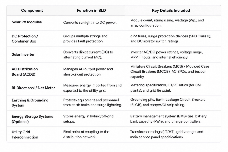
A professional solar SLD maps out power flowing sequentially through eight key component categories:
Standard SLD Electrical Symbols You Should Know
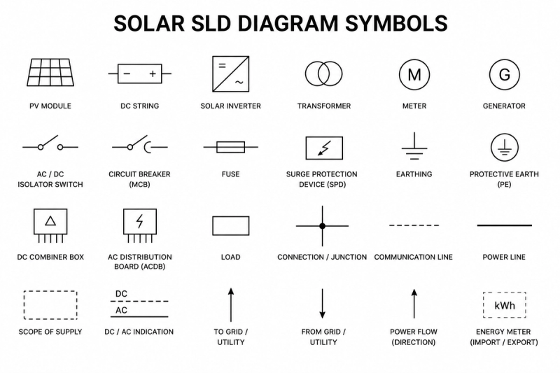
To maintain international readability, solar SLDs adhere to standardized drafting symbols defined by IEC 60617 or IEEE Std 315. Common symbols include:
- PV Module / Array: A rectangle with angled panel line hatches representing solar cells.
- Inverter (DC to AC): A square split diagonally, with a straight line (DC symbol) on one side and a sine wave (AC symbol) on the other.
- Circuit Breaker: A switch symbol with an automatic trip line or a box with breaker ratings.
- Disconnector / Isolator Switch: An open switch contact symbol showing isolation capability.
- Surge Protection Device (SPD): A box containing a diagonal arrow pointing toward the ground symbol.
- Ground / Earth Point: A vertical wire line terminating in three parallel horizontal lines of decreasing length.
The Old Way vs. The Modern Automated SLD Workflow
Historically, drafting a Single Line Diagram required a dedicated electrical CAD designer spending hours in AutoCAD or Visio for every single proposal or permit pack. If the customer decided to swap a 540W module for a 580W panel, or if the inverter model changed, the entire SLD had to be drawn from scratch.
The Solution: Instant SLD Generation via Solar Ladder Software
Modern solar EPCs no longer spend hours on manual drafting. With Solar Ladder's integrated 3D design and automation software, generating an accurate, compliant SLD takes seconds.
Here is how software automation transforms your engineering pipeline:
- Auto-Sync with 3D Layouts: When you design your solar array layout using Solar Ladder’s 3D Solar Design Software, the platform automatically calculates string counts, inverter matching, and electrical specs.
- One-Click SLD Generation: With a single click, Solar Ladder automatically constructs a compliant Single Line Diagram complete with standard IEC symbols, wire sizing, protection breaker ratings, and meter positions.
- Dynamic Modifications: If you update the module layout or switch equipment specs in your proposal, your SLD updates automatically across all project files.
- Zero CAD Skills Required: Sales representatives and project engineers can generate client-ready, permit-ready technical packs without relying on external design agencies.
How Solar Ladder Streamlines Your Entire EPC Workflow
Single Line Diagrams are just one cog in the operational engine of a successful solar company. To scale efficiently, your design tools must talk to your sales and execution teams.
Solar Ladder connects the entire workflow within one unified software platform:
- 3D Design & Auto-Proposals: Create shade-analyzed 3D designs in under 2 minutes and generate complete technical proposals with integrated SLD schematics instantly.
- Solar Lead & CRM Automation: Track customer interactions, quote versions, and permit submission stages seamlessly. Learn more about How Solar CRM Automation Saves 10+ Hours Every Week.
- Centralized Project Management: Stop tracking installations across messaging apps. Coordinate site surveys, DISCOM permit filings, SLD approvals, and installation tasks from a single dashboard. Discover how to Stop Managing Solar Projects on WhatsApp and Excel.
- Mobile App for On-Site Technicians: Give field crews instant access to approved SLD diagrams, component specifications, and milestone checklists directly on their phones.
Conclusion: Elevate Your Solar Engineering with Automated SLDs
A Solar Single Line Diagram is more than just lines on paper—it is the foundational electrical document that drives grid compliance, worker safety, and seamless installation. By automating SLD creation using specialized software, solar installers eliminate human error, drastically reduce design bottlenecks, and close projects faster.
Ready to experience effortless solar design and automated SLD generation? Try Solar Ladder Software today and transform how your solar team designs, manages, and executes solar projects!
Frequently Asked Questions
A Solar Single Line Diagram (SLD) provides a simplified electrical schematic of a solar PV system. Its main purpose is to clearly map component connections, protection devices, cable specs, and grid tie-in points for regulatory approvals, safe installation, and operational maintenance.
Yes, utility grid operators (DISCOMs) require a compliant SLD as a mandatory attachment to net-metering and grid interconnection applications to verify system safety and protection settings.
A wiring diagram shows physical wire connections, terminal numbers, and spatial routing of individual conductors. An SLD is a logical schematic that represents multi-wire or 3-phase circuits as a single line, making complex electrical architectures clean and easy to read at a glance.
Yes! Modern solar software platforms like Solar Ladder automatically generate accurate, compliant Single Line Diagrams directly from your 3D solar array layout, saving hours of manual CAD drawing time.
A complete solar SLD must include solar PV module string configurations, DC combiner boxes/isolators, string or central inverters, AC distribution boards (ACDB), circuit breakers/fuses, surge protection devices (SPD), earthing connections, bi-directional net meters, and utility grid connection points.